|
|
Recording macros is not available in all workbenches. |
Infrastructure |
Getting Started with Automation |
This article will show you how to use a scripting language to access CAA V5 automation objects to capture your own know-how and to increase your productivity. You can customize V5 applications to automate repetitive tasks, and to make it fit your own process.
The products that make up the CATIA and DELMIA applications share the same object model which can be accessed, as well as their own objects, by scripts written in Visual Basic with Windows, and scripts written in Basic Script for UNIX.
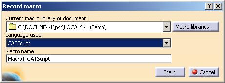
You can write your scripts from scratch, but you can also use the journalling facility from the Macros ... command in the Tools menu that records end-user scenarios in scripts you can then use as is or modify.
|
|
Recording macros is not available in all workbenches. |
We put here a simple script example, to show what is scripting, which are the different things to do to script, present briefly the scripting environment and dialog window, and what is journaling. This example is divided into the following parts:
You will then find information about the scripting languages and environments, and some keys for you if you are not familiar with writing macros in Invoking CATIA from a Scripting Language.
|
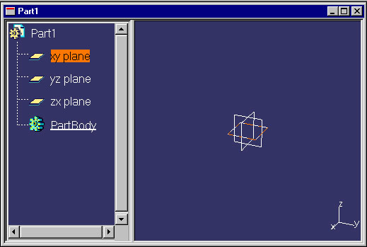
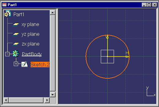
This scenario creates a circle in a sketch, and uses this sketch to create a cylindric pad. |
||
|
The recorded macro is stored in a file, and not in the document. |
||
|
||
|
||
|
||
|
 |
|
|
 |
|
|
||
|
||
|
 |
|
|
 |
|
|
||
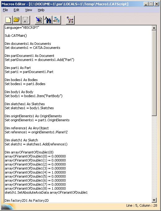
We detail below, line by line, what has been recorded, following the interactive steps. How to access the macro generated source is explained in the next step (Modifying the Generated Macro):
Language="VBSCRIPT"

Sub CATMain()
Dim documents1 As Documents
Set documents1 = CATIA.Documents

Dim partDocument1 As Document
Set partDocument1 = documents1.Add("Part")
A new document with the Part type is created. To do this, such a document
is added to the Documents collection of the CATIA
application.
Dim part1 As Part
Set part1 = partDocument1.Part

Dim bodies1 As Bodies
Set bodies1 = part1.Bodies

Dim body1 As Body
Set body1 = bodies1.Item("PartBody")
Dim sketches1 As Sketches Set sketches1 = body1.Sketches Dim originElements1 As OriginElements Set originElements1 = part1.OriginElements Dim reference1 As AnyObject Set reference1 = originElements1.PlaneXY Dim sketch1 As Sketch Set sketch1 = sketches1.Add(reference1) Dim arrayOfVariantOfDouble1(8) arrayOfVariantOfDouble1(0) = 0.000000 arrayOfVariantOfDouble1(1) = 0.000000 arrayOfVariantOfDouble1(2) = 0.000000 arrayOfVariantOfDouble1(3) = 1.000000 arrayOfVariantOfDouble1(4) = 0.000000 arrayOfVariantOfDouble1(5) = 0.000000 arrayOfVariantOfDouble1(6) = 0.000000 arrayOfVariantOfDouble1(7) = 1.000000 arrayOfVariantOfDouble1(8) = 0.000000 sketch1.SetAbsoluteAxisData arrayOfVariantOfDouble1 Dim factory2D1 As Factory2D Set factory2D1 = sketch1.OpenEdition()
A Sketch object named Sketch1 is added to the Sketches
collection using the reference1 Reference corresponding
to the XY plane as a support. Using a reference allows to create a sketch
either on an element, as here the XY plane, or on a solid planar face that
is not directly accessible as a VB object.
The SetAbsoluteAxisData method is used to define the
orientation of the sketch axis, that can be on either side and can rotate
inside of the support plane. A Factory2D object is created by opening
the sketch editor against the created sketch. This Factory2D object
features methods to create 2D objects.
Dim geometricElements1 As GeometricElements
Set geometricElements1 = sketch1.GeometricElements

Dim axis2D1 As GeometricElement
Set axis2D1 = geometricElements1.Item("AbsoluteAxis")

Dim line2D1 As AnyObject
Set line2D1 = axis2D1.GetItem("HDirection")

line2D1.ReportName = 1

Dim line2D2 As AnyObject
Set line2D2 = axis2D1.GetItem("VDirection")

line2D2.ReportName = 2
When the sketch is created, an axis, that is the aggregation of a center point, and horizontal line and vertical line (directions), is created.
The axis is retrieved in the GeometricElements collection of the Sketch
object, the directions are retrieved as objects aggregated by the axis. The
two lines are here assigned an identifier using their ReportName
property that will be used by the 3D modeling services to retrieve those
elements inside of the sketch. They have no end-user meaning.
Dim circle2D1 As Circle2D
Set circle2D1 = factory2D1.CreateClosedCircle(0.000000, 0.000000, 10.000000)

Dim point2D1 As AnyObject
Set point2D1 = axis2D1.GetItem("Origin")

circle2D1.CenterPoint = point2D1

circle2D1.ReportName = 3
The
CreateCloseCirclemethod of the Factory2D object is used to create the circle. It is first created as centered at the point (0,0) with a radius of 10 mm. It is then constraint on the axis center point using theCenterPointproperty.
    CATIASketch3.CloseEdition
    part1.Update
The sketch editor is closed and the part udapted.
Dim shapeFactory1 As Factory
Set shapeFactory1 = part1.ShapeFactory
Dim pad1 As Pad
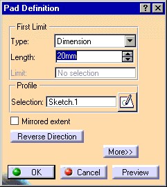
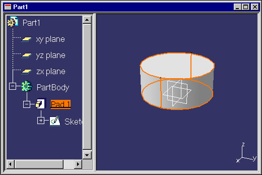
Set pad1 = shapeFactory1.AddNewPad(sketch1, 20.000000)
part1.Update
The AddNewPad method of the ShapeFactory object is
used to create the pad. It is created using the sketch and the length of
20mm. The part is updated.
This closes the macro recording sequence and saves the macro in the selected file.
This is all what you performed interactively in the previous chapter.
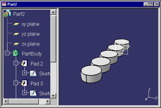
| This task explains how to modify the generated macro to make it loop on the creation of five identical cylindric pads. | ||
|
||
|
||
|
|
You can choose your own text editor to edit the macro by setting
the CATMacroEditor environment variable prior to launching CATIA
with the name of the editor program:set CATMacroEditor=NOTEPAD or using Control Panel/System/Environment on Windows, or: export CATMacroEditor=vi On Unix. This editor must be accessible through the PATH environment variable. Consult your administrator for more information on how to proceed.
|
|
|
||
|
||
| The source of the modified macro, CAAInfGettingStarted.CATScript,
is available in the CAAScdInfUseCases module. Execute
macro (windows only).
|
||
|
This task explains how to run the modified macro. |
|
|
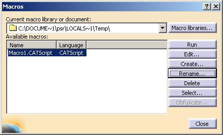
After exiting the Macro Editor, you're back in the Macros window:
|
|
This use case has shown how to record a macro, modify it and then launch its execution.
[Top]
| [1] | Adding a Macro as a Command in a Toolbar |
|
[Top] |
|