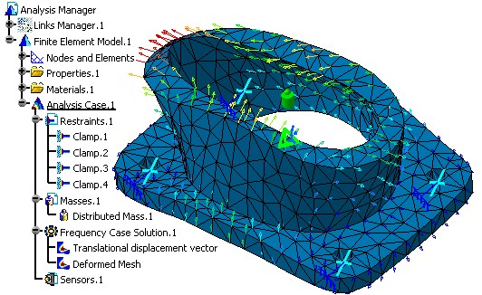
It creates an Analysis document, imports a Part document provided with the sample. An Analysis Case is created as for modal analysis. Some pre-processing data is defined by using the publication defined on the part. This example will focus on the creation of virtual parts. Then the virtual parts are clamped. On top of the design some additional mass is added. This example will also illustrate how to read pre-processing data.
CAAAniPreproOnVirtual.catvbs is located in the CAAScdAniUseCases module. Execute macro (Windows only).
- Prolog
- Importing the Part Document
- Creating an Analysis Case for Frequency Analysis
- Creating Virtual Parts inside the Property Set
- Defining Boundaries on the Virtual Parts
- Defining Non Structural Masses
- Computing the Case
- Epilog
Prolog
...
' -----------------------------------------------------------
' Get the collection of documents in session
' Create the CATAnalysis Document
   Set TheAnalysisDocument = documents1.Add("Analysis")

' if WB name already is "GPSCfg", not to use StartWorkbench
   WBName = CATIA.GetWorkbenchId
   if (WBName <> "GPSCfg") Then
      CATIA.StartWorkbench("GPSCfg")
   End If
 ...
|
Create the Analysis document. The use of StartWorkbench will customize the analysis document as a generative one. it mean's that a 3D meshpart and an isotropic property will be automatically created as in the Generative workbench.
Importing the Part Document
In order to import the document you have to give the path of this document, the late type which implements CATISamImportDefine and an array of CATVariant if you want to customize the import.
...
'_____________________________________________________________________________________
' Start to scan the existing structure of analysis document: Retrieve the AnalysisManager
   Set analysisManager1 = TheAnalysisDocument.Analysis
Dim arrayOfVariantOfShort1(0) analysisManager1.ImportDefineFile (sDocPath & "\online\CAAScdAniUseCases\samples\AnalysisMechfeat.CATPart"), "CATAnalysisImport", arrayOfVariantOfShort1
' _____________________________________________________________________________________
' Reframe All.
Set specsAndGeomWindow1 = CATIA.ActiveWindow
Set viewer3D1 = specsAndGeomWindow1.ActiveViewer
viewer3D1.Reframe
' _____________________________________________________________________________________
' Scan the analysis document: Retrieve the Pointed documents to extract the reference for preprocessing
Set analysisLinkedDocuments1 = analysisManager1.LinkedDocuments
CATIA.SystemService.Print analysisLinkedDocuments1.Name
If (analysisLinkedDocuments1.Count <> 1 ) Then
Err.Raise 9999,,"NbDoc Lié NE 1"
End If
' _____________________________________________________________________________________
' Retrieve the CATPart Document and associated publications for preprocessing.
Set TheDoc = analysisLinkedDocuments1.Item(1)
CATIA.SystemService.Print TheDoc.FullName
Set product1 = TheDoc.Product
Set publications1 = product1.Publications
...
|
The Part document is fetched in the documentation installation path,
this path has already been stored in the sDocPath variable.
In the collection of documents analysisLinkedDocuments1, two documents can
be retrieved: the Analysis document and the Part document. The extraction
of pre-defined geometrical arena is done by using the Publication
interface. Each publication is identified by a logical name. This is
equivalent as the selection of a Publication element inside the
interactive applications.
[Top]
Creating an Analysis Case for Frequency Analysis
According to the general Analysis Document structure, this macro uses some standard procedures to navigate or retrieve the required objects. First, from the document, we find the Analysis manager Object, the Analysis models and the Analysis cases Objects. From both last object (Analysis Model and Analysis case), you can get access to Analysis Sets and Analysis entities that defines the preprocessing actions.
Inserting a new Frequency Case allows you to create objects sets for the new environmental specifications, and to implicitly require a normal modes solution procedure for the computation of the system vibration frequencies and normal modes for a given non-structural mass distribution under given restraints
...
' _____________________________________________________________________________________
' Create a Case for frequency computation in the current analysis model.
   Set analysisModels1 = analysisManager1.AnalysisModels
   Set analysisModel1 = analysisModels1.Item(1)

   Set analysisCases1 = analysisModel1.AnalysisCases
   Set analysisCase1 = analysisCases1.Add()
   Set analysisSets1 = analysisCase1.AnalysisSets

   Set analysisSet1 = analysisSets1.Add("RestraintSet", catAnalysisSetIn)
   Set analysisSet2 = analysisSets1.Add("MassSet", catAnalysisSetIn)
   Set analysisSet3 = analysisCase1.AddSolution("FrequencySet")
   Set analysisSet6 = analysisSets1.Add("SensorSet",catAnalysisSetOut)
  ...
|
[Top]
Creating Virtual Parts inside the Property Set
Virtual Parts are structures created without a geometric support. They represent bodies for which no geometry model is available, but which play a role in the structural analysis of single part or assembly systems. Virtual Parts are used to transmit action at a distance. Therefore they can be thought of as rigid bodies, except for the case where a lumped flexibility is explicitly introduced by the means of a spring element. For each hole we, will create a Rigid virtual part in order to fix the global structure.
...
Set analysisSet4 = analysisSets2.ItemByType("PropertySet")

Set analysisEntities1 = analysisSet4.AnalysisEntities
Set analysisEntity1 = analysisEntities1.Add("SAMVirPartRigid")
Set publication1 = publications1.Item("SmallHole")
analysisEntity1.AddSupportFromPublication product1, publication1

...
|
[Top]
Defining Boundaries
  ...
' _____________________________________________________________________________________
' Clamp the Rigid Virtal Parts

   Set analysisEntities2 = analysisSet1.AnalysisEntities
   Set analysisEntity5 = analysisEntities2.Add("SAMClamp")
   Set reference1 = analysisManager1.CreateReferenceFromObject(analysisEntity4)
   analysisEntity5.AddSupportFromReference reference1, reference1
...
|
From the restraint set defined on the analysis case, we retrieve the collection of analysis entities. We add to this collection a fix (clamp) boundary condition and apply it on the virtual part. For this we have to create a reference on the analysis feature and use the AddSupportFromReference method. Then, same is done for the 3 other virtual parts.
[Top]
Defining Non Structural Masses
Distributed Masses are used to model purely inertial (non-structural) system characteristics such as additional equipment. They represent scalar point mass fields equivalent to a total mass concentrated at a given point, distributed on a virtual part or on a geometric selection. We apply this mass of the top surface.
...
' _____________________________________________________________________________________
' Distribute some Masses on top of the Part

   Set analysisEntities3 = analysisSet2.AnalysisEntities
   Set analysisEntity9 = analysisEntities3.Add("SAMDistributedMass")
   Set publication5 = publications1.Item("TopFace")
   analysisEntity9.AddSupportFromPublication product1, publication5

   Set basicComponents1 = analysisEntity9.BasicComponents
   Set basicComponent1 = basicComponents1.GetItem("SAMMassMag")
   basicComponent1.SetValue "", 0, 0, 0, 25.000000


' _____________________________________________________________________________________
' Read the Value of the Mass
  CATIA.SystemService.Print " Mass Applied of the Part: " & basicComponent1.GetValue ("",0,0,0)

...
|
Note that to valuate the parameters, you can SetValue method and to read them again, you can use the GetValue that will return the value stored in the document.
[Top]
Computing the Case
... ' Launch the computation of the Case MyCase.Compute ... ... |
This method will launch the mesher, generate the finite element model for preprocessing and launch the solver to generate the finite element results.
[Top]
Epilog
... End Sub |