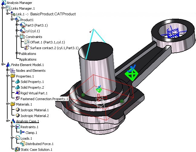
It creates an Analysis document, imports a Product document provided with the sample. An Analysis Case is created as for static linear analysis. Some preprocessing data are defined by using the publication defined on the product. We will focus on the creation of connection properties based on assembly constraints and creation of loading conditions based on rigid virtual part.
CAAAniPreproOnProduct.catvbs is located in the CAAScdAniUseCases module. Execute macro (Windows only).
- Prolog
- Importing the Product Document and Extract the Publications and Constraints
- Creating a Virtual Part and a Property Connection
- Creating an Analysis Case for Static Analysis
- Defining the Boundaries
- Defining the Load
- Extracting Data from a Basic Component
- Computing the Case
- Epilog
Prolog
... '_____________________________________________________________________________________
' Optional: allows to find the sample wherever it's installed
sDocPath=CATIA.SystemService.Environ("CATDocView")
sSep=CATIA.SystemService.Environ("ADL_ODT_SLASH")
If (Not CATIA.FileSystem.FolderExists(sDocPath)) Then
Err.Raise 9999,,"No Doc Path Defined"
End If
'_____________________________________________________________________________________
' Get the collection of documents in session
Set documents1 = CATIA.Documents
' -----------------------------------------------------------
' Get the collection of documents in session
' Create the CATAnalysis Document
Set TheAnalysisDocument = documents1.Add("Analysis")
' if WB name already is "GPSCfg", not to use StartWorkbench
WBName = CATIA.GetWorkbenchId if (WBName <> "GPSCfg") Then
CATIA.StartWorkbench("GPSCfg")
End If
...
|
Create the Analysis document. The use of StartWorkbench will customize the analysis document as a generative one. This means that meshparts and properties will be automatically created as in the Generative workbench.
Importing the Product Document and Extracting the Publications
In order to import the document you have to give the path of this document,
the late type which implements CATISamImportDefine and an array of CATVariant
if you want to customize the import.
...
' Start to scan the existing structure of analysis document:  Retrieve the AnalysisManager
  Set analysisManager1 = TheAnalysisDoc.Analysis
Dim arrayOfVariantOfShort1(0)
analysisManager1.ImportDefineFile (sDocPath & sSep & "online" & sSep & "CAAScdAniUseCases"
& sSep & "samples" & sSep & "basic_assembly.CATProduct"),
 				     "CATAnalysisImport", arrayOfVariantOfShort1

' _____________________________________________________________________________________
' Reframe All.
  Set specsAndGeomWindow2 = CATIA.ActiveWindow
  Set viewer3D1 = specsAndGeomWindow2.ActiveViewer
  viewer3D1.Reframe


' _____________________________________________________________________________________
' Scan the analysis document:  Retrieve the Pointed documents to extract the reference for preprocessing
  Set analysisLinkedDocuments1 = analysisManager1.LinkedDocuments
  CATIA.SystemService.Print analysisLinkedDocuments1.Name
  If (analysisLinkedDocuments1.Count <> 1 ) Then
    Err.Raise 9999,,"NbDoc Lié NE 1"
  End If

' _____________________________________________________________________________________
' Retrieve the CATProduct Document and associated publications and constraints collection.

  Set productDocument1 = analysisLinkedDocuments1.Item(1)

  Set product1 = productDocument1.Product
  Set products1 = product1.Products

  Set publications1 = product1.Publications
  Set constraints1 = product1.Connections("CATIAConstraints")
...
|
The product document is fetched in the documentation installation path,
this path has already been stored in the sDocPath variable.
In the collection of documents analysisLinkedDocuments1, two documents can
be retrieved: the Analysis document and the Product document. The extraction
of pre-defined geometrical arena is done by using the Publication interface.
Each publication is identified by a logical name. This is equivalent as
the selection of a Publication element inside the interactive applications.
Other used support is the assembly constraints. For this we also extract
from the product the constraints collection.
[Top]
Creating a Virtual Part and a Property Connection
Virtual Parts are structures created without a geometric support. They represent bodies for which no geometry model is available, but which play a role in the structural analysis of single part or assembly systems. Virtual Parts are used to transmit actions at a distance. Therefore they can be thought of as rigid bodies, except for the case where a lumped flexibility is explicitly introduced by the means of a spring element. For each hole we will create a Rigid virtual part in order to distribute a global force to a linked face.
...
' _____________________________________________________________________________________
' Create a Virtual Part in the analysis model to transmit the load.
Set analysisSets1 = analysisModel1.AnalysisSets
Set analysisSet1 = analysisSets1.ItemByType("PropertySet")

Set analysisEntities1 = analysisSet1.AnalysisEntities
Set analysisEntity1 = analysisEntities1.Add("SAMVirPartRigid")
Set publication1 = publications1.Item("FaceCylinderTop")
analysisEntity1.AddSupportFromPublication product1, publication1
Set basicComponents1 = analysisEntity1.BasicComponents
Set basicComponent1 = basicComponents1.GetItem("SAMRigSlavePoint.1")
Set publication4 = publications1.Item("ForceHandler")
basicComponent1.AddSupportFromPublication product1, publication4

...
|
Connections properties are assembly connections used to specify the boundary interactions between bodies in an assembled system. Once the geometric assembly positioning constraints are defined at the Product level, the user can specify the physical nature of the constraints. We will use in this scenario a Fastened Connection that represents the link between two bodies which are fastened together at their common boundary, and will behave as if they were a single body. From a finite element model viewpoint, this is equivalent to the situation where the corresponding nodes of two compatible meshes are merged together. However, since bodies can be meshed independently, the Fastened Connection is designed to handle incompatible meshes.
...
' _____________________________________________________________________________________
' Create a Fastened connection in the analysis model to complete the constraints
' definition
Set analysisEntity2 = analysisEntities1.Add("SAMFaceFaceFastened")
Set constraint1 = constraints1.Item("Surface contact.2")
analysisEntity2.AddSupportFromConstraint product1, constraint1

...
|
[Top]
Creating an Analysis Case for Static Analysis
...
' _____________________________________________________________________________________
' Create a Static Case in the current analysis model.
   Set analysisModels1 = analysisManager1.AnalysisModels
   Set analysisModel1 = analysisModels1.Item(1)
   Set analysisCases1 = analysisModel1.AnalysisCases

   Set analysisCase1 = analysisCases1.Add()
   Set analysisSets1 = analysisCase1.AnalysisSets
   Set analysisSet1 = analysisSets1.Add("RestraintSet", catAnalysisSetIn)
   Set analysisSet2 = analysisSets1.Add("LoadSet", catAnalysisSetIn)
   Set analysisSet3 = analysisCase1.AddSolution("StaticSet")
  ...
|
According to the general Analysis Document structure, this macro uses some standard procedures to navigate or retrieve the required objects. First, from the document, we find the Analysis manager Object, the Analysis models and the Analysis cases Objects. From both last object (Analysis Model and Analysis case), you can get access to Analysis Sets and Analysis entities that defines the preprocessing actions. This step create a new case and create two input sets (Restraint Set and Load Set) and a solution set (StaticSet).
[Top]
Defining the Boundaries
  ...
' _____________________________________________________________________________________
' Create clamp boundary. Associated to a publication
Set analysisEntities2 = analysisSet2.AnalysisEntities
Set analysisEntity3 = analysisEntities2.Add("SAMClamp")
Set publication2 = publications1.Item("FaceToClamp")
analysisEntity3.AddSupportFromPublication product1, publication2
...
|
From the restraint set defined on the analysis case, we retrieve the collection of analysis entities. We add to this collection a fix (clamp) boundary condition and apply it on the geometry extracted from the Product document.
[Top]
Defining the Loads
...
' _____________________________________________________________________________________
' Create load boundary. Associated to the virtual part
Set analysisEntities3 = analysisSet3.AnalysisEntities

Set analysisEntity4 = analysisEntities3.Add("SAMDistributedForce")
Set reference2 = analysisManager1.CreateReferenceFromObject(analysisEntity1)
analysisEntity4.AddSupportFromReference reference2, reference2

Set basicComponents2 = analysisEntity4.BasicComponents
Set basicComponent2 = basicComponents2.GetItem("SAMForceAxis.1")
basicComponent2.SetValue "Values", 0, 0, 0, 1
Set basicComponent3 = basicComponents2.GetItem("SAMForceVector.1")
basicComponent3.SetDimensions 3, 1, 1
basicComponent3.SetValue "", 1, 1, 1, 100.000000
basicComponent3.SetValue "", 2, 1, 1, 0.000000
basicComponent3.SetValue "", 3, 1, 1, 0.000000
...
|
The load is defined as the boundaries. In this case the support is the virtual part created before. To use the method with a Reference use AnalysisManager.CreateReferenceFromObject that will transform the analysis entity into a reference.
[Top]
Extracting Data from a Basic Component
...
' Some examples to read the data on the basic component
'In this case, direct read
CATIA.SystemService.Print " ForceVector " & basicComponent3.GetValue("", 1, 1, 1)
CATIA.SystemService.Print " ForceVector " & basicComponent3.GetValue("", 2, 1, 1)
CATIA.SystemService.Print " ForceVector " & basicComponent3.GetValue("", 3, 1, 1)

CATIA.SystemService.Print " ForceVector Type " & basicComponent3.Type
CATIA.SystemService.Print " ForceVector Dimension " & basicComponent3.GetLinesNumber  ("")
CATIA.SystemService.Print " ForceVector Dimension " & basicComponent3.GetColumnsNumber("")
CATIA.SystemService.Print " ForceVector Dimension " & basicComponent3.GetLayersNumber ("")

'In this case, use the Kwe CATIAParameter interface.
Set ParametersList = analysisManager1.Parameters
Set SubList = ParametersList.SubList(basicComponent3,FALSE)

For i = 1 to SubList.Count
	Set Parameter = SubList.Item(i)
	CATIA.SystemService.Print Parameter.Name
	CATIA.SystemService.Print Parameter.ValueAsString
Next

...
|
[Top]
Computing the Case
... ' Launch the computation of the Case MyCase.ComputeMeshOnly ... ... |
This method will launch the mesher, generate the finite element model for preprocessing.
[Top]
Epilog
...End Sub ... |
To run the macro interactively CATDocView and ADL_ODT_SLASH environment variables must be defined.