It creates an Analysis document, imports a Part document provided with the sample. An Analysis Case is created as for static linear analysis. Some pre-processing data are defined by using the publication defined on the part. This example will focus on the usage of mapping surface forces. For this we will use the Design table object. Then, the computation is launched. A parameter that measures the maximum value of this stress is created and its value is printed.
CAAAniPreproMapping.catvbs is located in the CAAScdAniUseCases module. Execute macro (Windows only).
- Prolog
- Importing the Part Document and Extracting the Publication
- Creating an Analysis Case for Static Analysis
- Defining the Boundaries
- Defining the Load
- Computing the Case
- Defining a Sensor and Printing it's Value
- Epilog
Prolog
... ' -----------------------------------------------------------
' Optional: allows to find the sample wherever it's installed
sDocPath=CATIA.SystemService.Environ("CATDocView")
sSep=CATIA.SystemService.Environ("ADL_ODT_SLASH")
If (Not CATIA.FileSystem.FolderExists(sDocPath)) Then
Err.Raise 9999,,"No Doc Path Defined"
End If
' -----------------------------------------------------------
' Get the collection of documents in session
    Set documents1 = CATIA.Documents

' -----------------------------------------------------------
' Get the collection of documents in session
' Create the CATAnalysis Document
   Set TheAnalysisDocument = documents1.Add("Analysis")

' if WB name already is "GPSCfg", not to use StartWorkbench
   WBName = CATIA.GetWorkbenchId
   if (WBName <> "GPSCfg") Then
      CATIA.StartWorkbench("GPSCfg")
   End If
 ...
|
Create the Analysis document. The use of StartWorkbench will customize the Analysis document as a generative one. This means that meshparts and properties will be automatically created as in the Generative workbench.
Importing the Part Document and Extracting the Publications
In order to import the document you have to give the path of this document, the late type which implements CATISamImportDefine and an array of CATVariant if you want to customize the import.
...
'_____________________________________________________________________________________
' Start to scan the existing structure of analysis document: Retrieve the AnalysisManager
   Set analysisManager1 = TheAnalysisDocument.Analysis
Dim arrayOfVariantOfShort1(0) analysisManager1.ImportDefineFile (sDocPath & sSep & "online" & sSep & "CAAScdAniUseCases" & sSep & "samples" & sSep & "SimpleCrank.CATPart"), "CATAnalysisImport", arrayOfVariantOfShort1
' _____________________________________________________________________________________
' Reframe All.
Set specsAndGeomWindow1 = CATIA.ActiveWindow
Set viewer3D1 = specsAndGeomWindow1.ActiveViewer
viewer3D1.Reframe
' _____________________________________________________________________________________
' Scan the analysis document: Retrieve the Pointed documents to extract the reference for pre-processing
Set analysisLinkedDocuments1 = analysisManager1.LinkedDocuments
CATIA.SystemService.Print analysisLinkedDocuments1.Name
If (analysisLinkedDocuments1.Count <> 1 ) Then
Err.Raise 9999,,"NbDoc Lié NE 1"
End If
' _____________________________________________________________________________________
' Retrieve the CATPart Document and associated publications for pre-processing.
Set TheDoc = analysisLinkedDocuments1.Item(1)
CATIA.SystemService.Print TheDoc.FullName
Set product1 = TheDoc.Product
Set publications1 = product1.Publications
Set publication1 = publications1.Item("ClampFace")
Set publication2 = publications1.Item("MappingFace")
...
|
The Part document is fetched in the documentation installation path,
this path has already been stored in the sDocPath variable.
In the collection of documents analysisLinkedDocuments1, two documents can
be retrieved: the Analysis document and the Part document. The extraction
of pre-defined geometrical arena is done by using the Publication interface.
Each publication is identified by a logical name. This is equivalent as
the selection of a Publication element inside the interactive applications.
[Top]
Creating an Analysis Case for Static Analysis
...
' _____________________________________________________________________________________
' Create a Static Case in the current analysis model.
   Set analysisModels1 = analysisManager1.AnalysisModels
   Set analysisModel1 = analysisModels1.Item(1)
   Set analysisCases1 = analysisModel1.AnalysisCases

   Set analysisCase1 = analysisCases1.Add()
   Set analysisSets1 = analysisCase1.AnalysisSets
   Set analysisSet1 = analysisSets1.Add("RestraintSet", catAnalysisSetIn)
   Set analysisSet2 = analysisSets1.Add("LoadSet", catAnalysisSetIn)
   Set analysisSet3 = analysisCase1.AddSolution("StaticSet")
  ...
|
According to the general Analysis Document structure, this macro uses some standard procedures to navigate or retrieve the required objects. First, from the document, we find the Analysis manager Object, the Analysis models and the Analysis cases Objects. From both last object (Analysis Model and Analysis case), you can get access to Analysis Sets and Analysis entities that defines the pre-processing actions. This step create a new case and create two input sets (Restraint Set and Load Set) and a solution set (StaticSet).
[Top]
Defining the Boundaries
  ...
' To work with the collection of entities that defines the Boundary condition.
' _____________________________________________________________________________________
   Set analysisEntities1 = analysisSet1.AnalysisEntities
   Set analysisEntity1 = analysisEntities1.Add("SAMClamp")
   analysisEntity1.AddSupportFromPublication product1, publication1
...
|
From the restraint set defined on the analysis case, we retrieve the collection of analysis entities. We add to this collection a fix (clamp) boundary condition and apply it on the geometry extracted from the Part document. Then, same is done for the sliding conditions.
[Top]
Defining the Loads
...
' _____________________________________________________________________________________
' Create Surfacic Force and apply to the publication called MappingFace

   Set analysisEntities2 = analysisSet2.AnalysisEntities
   Set analysisEntity3 = analysisEntities2.Add("SAMSurfacicForce")

   analysisEntity3.AddSupportFromPublication product1, publication2

   Set basicComponents1 = analysisEntity3.BasicComponents

' No Local Axis is defined
   Set basicComponent1 = basicComponents1.GetItem("SAMSurfacicForceAxis.1")
   basicComponent1.SetValue "", 0, 0, 0, 1

' Valuate the vector.
   Set basicComponent2 = basicComponents1.GetItem("SAMSurfacicForceVector.1")
   basicComponent2.SetValue "Values", 1, 1, 1, 0.000000
   basicComponent2.SetValue "Values", 2, 1, 1, -1000000.000000
   basicComponent2.SetValue "Values", 3, 1, 1, 0.000000

' Create a Design Table for the mapping file and valuate the basic component
   Set basicComponent3 = basicComponents1.GetItem("SAMDTPtrSurfForce")
   Set designTable1 = analysisManager1.Relations.CreateDesignTable("", "", False, sDocPath & sSep  & "online" &
                                 sSep & "CAAScdAniUseCases" & sSep & "samples" & sSep  & "MappingForCrank.txt")
   basicComponent3.SetValue "", 0, 0, 0, designTable1

...
|
The load is defined as the boundaries. For the mapping file, we will use the DesignTable object. This object is created with the collection of Relations. This collection is available on the AnalysisManager object by using analysisManager1.Relations method.
For more information about the physical types included inside analysis entities and the way to valuate them, refer to the reference [2]
[Top]
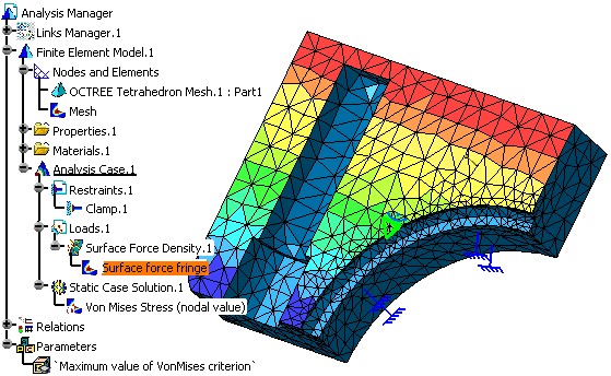
Computing the Case
... ' Launch the computation of the Case MyCase.Compute ... |
This method will launch the mesher, generate the finite element model for pre-processing and launch the solver to generate the finite element results.
[Top]
Defining a Sensor and Printing it's Value
...
' _____________________________________________________________________________________
' Define a global sensor measuring the maximum value of VonMises criterion.
   Set dimension1 = analysisManager1.Parameters.CreateDimension("Maximum value of VonMises criterion", "PRESSURE", 0.000000)
   Set formula1 = analysisManager1.Relations.CreateFormula("Maximum value of VonMises criterion","",dimension1,
                                                 "misesmax(`Finite Element Model.1\Static Case Solution.1` ) ")
' Extract the computed value of the sensor
   CATIA.SystemService.Print " Mises Max Computed " & dimension1. ValueAsString
...
|
Epilog
...End Sub ... |
To run the macro interactively CATDocView and ADL_ODT_SLASH environment variables must be defined.