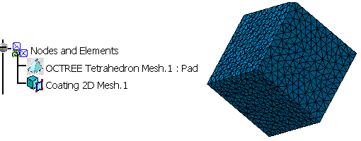
This use case shows you how to create coating 2D mesh part by extracting face elements of an existing 3D mesh part. A coating mesh can be extracted from a octree tetrahedron mesh part, tetrahedron filler mesh part, 3D transformed mesh part. This functionality is available in FEM Solid (FMD) product.
The macro opens an Analysis document which already contains octree tetrahedron mesh part. The coating mesh is created over this mesh part. The mesh part is updated to generate coating mesh.

CAAAniMeshCoating2D is launched in CATIA [1]. No open document is needed.
CAAAniMeshCoating2D.catvbs is located in the CAAScdAniUseCases module. Execute macro (Windows only).
CAAAniMeshCoating1D includes the following steps:
- Prolog
- Extracting the List of Mesh Parts and Publications
- Creating Mesh part and Assigning Values to its Attributes
- Epilog
Prolog
... '-----------------------------------------------------------
'Optional: allows to find the sample wherever it's installed
sDocPath=CATIA.SystemService.Environ("CATDocView")
If (Not CATIA.FileSystem.FolderExists(sDocPath)) Then
Err.Raise 9999,,"No Doc Path Defined"
End If
'-----------------------------------------------------------
'Open the Analysis document
sFilePath = CATIA.FileSystem.ConcatenatePaths(sDocPath, "online\CAAScdAniUseCases\samples\Cube_R13_Freq.CATAnalysis")
Set oAnalysisDocument = CATIA.Documents.Open(sFilePath)
... |
Open the Analysis document. The Analysis document is fetched in the documentation
installation path, this path is already stored in the sDocPath
variable. If this variable is not valuated then error is raised. In the collection of documents, two documents can be retrieved:
the Analysis document and the Part document.
Extracting the List of Mesh Parts and Publications
... 'Retrieve the analysis Manager Set oAnalysisManagar = oAnalysisDocument.Analysis 'Retrieve the part document and product Set oAnalysisLinkedDocuments = oAnalysisManagar.LinkedDocuments Set partDocument = oAnalysisLinkedDocuments.Item(1) Set product = partDocument.Product
'Retrieve the published face
Set publications1 = product.Publications
Set pubFace = publications1.Item("Top")

'Retreive the analysis model
Set oAnalysisModels = oAnalysisManagar.AnalysisModels
Set oAnalysisModel = oAnalysisModels.Item(1)

'Retrive The mesh manager and the list of mesh parts
Set oAnalysisMeshManager = oAnalysisModel.MeshManager
Set oAnalysisMeshParts = oAnalysisMeshManager.AnalysisMeshParts

'Retrieve the already existing Octree mesh part
Set oAnalysisMeshPart = oAnalysisMeshParts.Item(1)
'Create reference from the mesh part Set reference1 = oAnalysisManager.CreateReferenceFromObject(oAnalysisMeshPart) ... |
According to the general Analysis Document structure, this macro uses some standard procedures to navigate or retrieve the required objects. First, from the Document, we find the Analysis Manager Object, the Analysis Models and the Mesh Manager Objects. The extraction of pre-defined geometric elements is done by using the Reference interface. This is equivalent to the selection of a B-Rep elements inside the interactive application. In this macro the reference is created from the octree tetrahedron mesh part.
Creating the Mesh Part and Assigning Values to its Attributes.
...

'Add the new Coating mesh part to the list of mesh parts
Set coat2D = oAnalysisMeshPart.Add ("MSHPart2DCoating")

'Set the reference to the surface mesh part
coat2D.AddSupportFromReference product, reference1

'Assign value to the global specification
coat2D.SetGlobalSpecification "ExtractionType", 1
'Add the local specification
Set meshSpecs = coat2D.AnalysisMeshLocalSpecifications
Set spec = meshSpecs.Add("MSHCoatingLocalSpecification")
spec.SetAttribute "LocalExtractionType", 2

spec.AddSupportFromPublication "ConnectorList", product, pubFace


'Update the mesh part
coat2D.Update

...
|
The local specification specifies the faces which are to be included or excluded while computing the coating mesh. You can specify multiple faces to one local specification. If you want to include some faces, and exclude some other then you need to create at least two local specifications. All the faces which are to be included, can be added as support to one local specification with the attribute "LocalExtractionType" valuated to 1. Similarly faces which are to be exclude can be added as support to other local specification with the attribute "LocalExtractionType" valuated to 2.
Epilog
... End Sub ... |
To run the macro interactively CATDocView environment variables must be defined. After running the macro the mesh may not be immediately visible, the user has to go to the Advanced Meshing Tools workbench to see the mesh.